

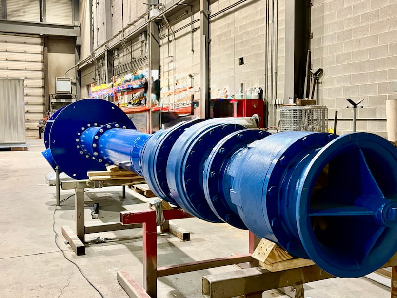
Vertical turbine pumps (VTPs) are the powerhouses behind some of the most critical water systems, including municipal water supplies, agricultural irrigation networks, and industrial fire protection systems. They run underground, often for decades, pulling water from depths that no other pump type can reliably reach.
But how does a vertical turbine pump work? This guide breaks down the pump’s mechanics and how it moves groundwater to the surface, building pressure at every stage to deliver water to the systems that rely on it.
Vertical Pumps: Built to Reach Water Where Other Pumps Can’t
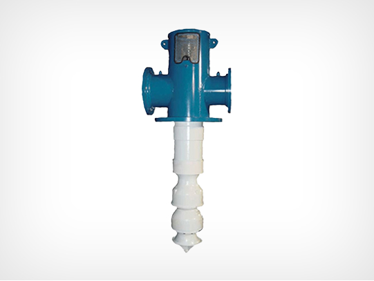
A VTP is a type of vertical centrifugal pump designed for high-pressure applications, in which the water supply sits below the pump rather than beside it. The pump body, including the bowl assembly and rotating impellers, is submerged in a well, tank, or reservoir, while the drive equipment, usually an electric motor, sits above the surface. Water travels upward through the pump and exits through the discharge head at ground level.
This design sets vertical pumps apart from horizontal centrifugal pumps, which draw water in from the side at a fixed elevation. Because the pump itself is inserted from the top down into the water source, a vertical turbine pump can reach water in deep wells and deep pits that a horizontal pump can’t access.
Typical Applications of Vertical Turbine Pumps
Vertical turbine pumps are used across municipal water systems, fire protection, agricultural irrigation, and industrial process water, largely because they can reach deep sources and deliver high pressure over long distances.
Fire Protection
In fire protection, these pumps are well-suited to facilities where the water source sits below ground, and the system requires accessing the water without using suction lift to reach it; VTPs are widely used in fire pump packages for this reason.
Municipal
In municipal applications, vertical turbine pumps draw raw water from rivers, lakes, or underground sources into treatment plants and move finished, treated water to distribution systems.
Agriculture
In agriculture, vertical pumps lift groundwater from deep wells for irrigation across large-scale water systems.
Industrial Plants
Industrial plants use VTPs for general process water needs wherever the water source sits below the equipment. Common applications include cooling water systems, boiler feed water, and water supply for manufacturing processes.
Inside a Vertical Turbine Pump: How It Moves Water from Source to Surface
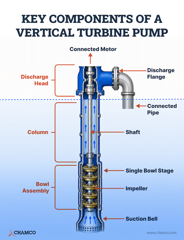
A vertical turbine pump uses a rotating shaft to drive submerged impellers that push water up a long column pipe to a discharge head at the surface. The process moves through five stages:
Step 1: The motor turns the shaft
The electric motor or diesel engine at the surface turns the rotating shaft, also called the line shaft, which runs the full length of the column. In a typical installation, the shaft diameter is much smaller than the column itself; a 12-inch-diameter column might contain a shaft only 1.5 inches across.
Step 2: The shaft drives the impellers
That shaft spins the impellers in the bowl assembly, which sits below the water line. Water enters and is drawn through the bell-shaped suction head at its base.
Step 3: The impellers move water to build pressure
Each spinning impeller uses centrifugal force to throw water outward into a stationary diffuser casing, also called a diffuser bowl, which converts that motion into pressure and directs the flow upward toward the next impeller.
Step 4: Pressure continues to build stage by stage
Each impeller and diffuser stage adds pressure before passing the water to the next stage. By stacking multiple stages, the pump can generate the high discharge pressures required for deep wells and high-head applications. The pressurized water then travels up the column pipe to the surface.
Step 5: Water exits at the discharge head
Water reaches the discharge head at the surface and exits through the discharge flange into the connected piping. Some installations route the discharge above floor level; others direct it sideways into a pipe running below the floor, depending on the facility’s layout.
Choosing the Right VTP Configuration
The choice between open and enclosed line shaft often comes down to one question: what’s in your water?
The answer determines whether your bearings run in direct contact with the pumped fluid or stay isolated from it behind a protective inner tube.
An Open Line Shaft
An open-line shaft pump runs the shaft and bearings directly inside the column pipe in contact with the water being pumped. The bearings are typically spaced every five to ten feet along the column and are lubricated by the pumped water itself, making this the more cost-effective option for clean water applications.
An Enclosed Line Shaft
An enclosed line shaft pump adds an inner tube within the column, keeping the shaft and bearings separate from the water. The shaft rotates inside an enclosing tube, while a separate supply of oil or clean water lubricates the bearings. This configuration costs more to build but holds up better in abrasive or contaminated water, since the bearings never come into contact with grit or debris.
A typical water treatment facility illustrates the trade-off well. Raw water drawn from a river often contains sand and silt, so enclosed line shaft pumps are commonly used for the intake because they protect the bearings from abrasive particles. After the water has been filtered, other parts of the facility may use open-line-shaft pumps, in which clean water can safely lubricate the bearings without causing excessive wear.
Factors That Affect Pump Performance
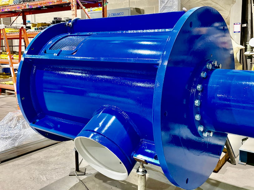
A vertical turbine pump’s performance in the field is shaped by three main factors: how its internal components wear over time, the quality of the water it pumps, and atmospheric conditions at the site.
Wear Over Time
Output is highest on day one. Vertical turbine pumps wear primarily at the clearances between moving and stationary parts. As internal clearances widen between the impeller and bowl, more water recirculates inside the pump rather than moving forward, causing a gradual drop in flow, pressure, and efficiency.
Clearance Tolerance
Wear isn’t the only clearance risk. If internal tolerances are set too tight during manufacturing or a rebuild, the pump can seize or gall almost immediately after startup, resulting in sudden failure rather than gradual decline. A precise clearance specification is just as important as monitoring wear over time.
Water Quality
Water quality affects performance independently of pressure and staging. Abrasive particles suspended in the water erode impellers and bowl surfaces over time, accelerating the widening of clearance that drives efficiency loss. High mineral content can cause deposits to form inside the pump, gradually restricting flow. Both issues develop slowly and are best managed through routine inspection and appropriate line shaft configuration. Enclosed line shaft pumps offer better protection in areas with poor water quality.
Weather And Atmospheric Pressure
Atmospheric pressure shifts with weather systems, and the swing between a severe high-pressure and a severe low-pressure system can change available suction pressure by 3 to 3.5 psi. This is enough to affect pump selection. Rather than assuming a fixed atmospheric pressure value, pump selection should include a margin of at least 3 feet between NPSHA and NPSHR, with a larger margin providing additional protection against weather-related pressure swings.
Lifespan And Rebuild Intervals
Rebuild intervals typically range from 1 to 20 years and vary by application and water quality, while total pump lifespan can range from 3 to 60 years, depending on maintenance. A consistent maintenance schedule is the most reliable way to extend the service life of a vertical turbine pump.
Work with Western Canada’s Vertical Turbine Pump Experts
Selecting a vertical turbine pump isn’t just a matter of matching flow and pressure specs to a product page. The right configuration depends on your water source depth, water quality, application demands, and long-term service expectations, and getting that specification wrong costs far more than a second opinion upfront.
Chamco has supplied and serviced vertical pumps across Western Canada for over 65 years. As the exclusive Western Canadian distributor for Peerless Pumps, Chamco is one of the few suppliers in Western Canada capable of engineering and designing complete vertical turbine systems and fire pump solutions. Our pump specialists have hands-on experience across municipal, agricultural, industrial, and fire protection applications. Whatever your water source, pressure requirements, or site conditions, we’ve likely solved a similar problem before.
With six service centres across BC and Alberta, a 40,000-square-foot ISO 9001:2015-certified production facility in Calgary, and an extensive OEM parts inventory stocked across Western Canada, Chamco supports the full life of your equipment, from initial specification through installation, commissioning, preventative maintenance, and rebuild service.
Contact us for help finding the right vertical turbine pump for your application.
Frequently Asked Questions
What is NPSHA, and why does it matter for vertical turbine pumps?
NPSHA stands for Net Positive Suction Head Available. It represents the total pressure pushing water toward the pump inlet, accounting for atmospheric pressure and subtracting any forces opposing flow, such as elevation change, pipe friction, and fluid temperature. For a vertical pump to operate properly, NPSHA must exceed NPSHR (the minimum inlet pressure specified by the pump manufacturer) by at least 3 feet, with a larger margin preferred. When NPSHA drops below NPSHR, the pump cavitates: vapour pockets form and collapse inside the pump, causing noise, vibration, and impeller damage over time. Vertical turbine pumps are designed with the bowl assembly submerged below the water source, specifically to keep NPSHA as high as possible.
What role does the water table play in vertical turbine pump performance?
Water table conditions directly affect NPSHA, the suction pressure available at the pump inlet. A falling water table increases the vertical distance water must travel to reach the pump, reducing the available pressure and narrowing the margin between NPSHA and NPSHR. This is why water-table conditions are an important consideration when selecting a pump, particularly for wells or sources where the water level can fluctuate seasonally or with extended use.
What are the Affinity Laws, and how do they apply to a vertical turbine pump?
The Affinity Laws are a set of mathematical rules that describe how a centrifugal pump’s flow, pressure, and power consumption change with rotational speed. For a vertical turbine pump operating at a fixed speed, increasing flow decreases pressure, and increasing pressure decreases flow. If the pump’s speed is reduced, pressure drops at any given flow rate. These relationships are why a single pump performance curve can include multiple lines, each representing the pump’s behaviour at a different operating speed.
What does a pump performance curve tell you?
A pump performance curve maps the relationship between flow, pressure, and rotational speed for a specific pump model, showing what it can deliver under any given operating condition. The curve is governed by the Affinity Laws and is specific to the bowl-and-impeller design of that pump.
A few things the curve reveals in practice: adding stages increases pressure without changing flow rate, so engineers meet high-head requirements by stacking impeller stages rather than redesigning the pump. The curve also serves as a baseline for monitoring wear. Output is highest on day one and then declines, so operators track current flow and pressure against the original curve to catch problems early.